
Limited workshop space, unlimited interests... "The Littlest Workshop" the bastard child of "The Little House On The Prairie" and "The Littlest Hobo" TV shows. My interests include EDM, CNC, Camping, injection moulding, welding, inventing, casting, bushcraft, composites, 3D printing, micro-RC, ornithopters, optics, microcontrollers, Ukulele, lock picking, cycling, safe cracking, motorcycle restoration ... Maybe tomorrow my projects will be finished?
Thursday 29 November 2012
Creepy but amazing
Theo Jansen's mechanical creatures are amazing and this one comes straight out of a 3D printer ready to "roll"
Wednesday 12 September 2012
Really sucks
The dust shroud shown in the previous post works really well but only if you have suction and can keep it. Last summer I pimped my shop vac with a cyclone because it would clog in seconds especially when doing wood work. Thought I should actually show it:
Cyclone vacuum systems seem a bit mysterious but are really not. First how do vacuums work? Well they move air with an impeller, speeding it up and creating a region of low pressure. Atmospheric pressure (the pressure caused by having a sky full of air above us) then pushes air into that region. So the impeller creates an air flow. This picks up dust simply because the dust becomes entrained in the flow of air. So in my shop vac the bag is in a chamber from which the air is sucked, this creates a flow of air through the nozzle and through the bag and out of this chamber. The bag acts as a filter. The problem is that it fills quickly and soon becomes clogged as fine particles get stuck in the pores.
A cyclone system uses the fact that the dust only moves within moving air. If you watch the video and understand the construction then air must flow from the tangential intake on the side of the cone to the vertical tube which ends about halfway down the cone. The high velocity of the air, the tangential inlet and the shape of the cone means the flow has to turn. Particles that are neutrally buoyant will follow the flow perfectly but anything with a bit of mass to it will tend not to turn and carry on straight, leaving the flow before hitting the cone's side and flowing down into the collection bin. So most of the dirt ends up in the bucket rather than going up the tube into the vacuum. Actually as a side note, cyclones are used to extract neutrally buoyant bubbles from bubble generators for use in flow visualization, they use tiny 3mm or so bubbles full of helium, they follow the flow so well that even when streamed over a wing at high speed they do not hit the wing and pop, they will even go through fans etc. In those devices the bucket is just collecting soap solution from popped bubbles which are flung outwards.
dust to dust
I'm just trying to move in to the not so littlest workshop, to make more space I am moving a partition wall closer to the stairs it surrounds. This revealed bare concrete floor, the rest of the floor is epoxy coated but that also looked pretty shabby. So I got quotes for a new epoxy floor, ouch! DIY it is then! Step one, remove all the old epoxy floor. I hired a diamond grinder, this got rid of the bulk without too much fuss and the dust extraction kept things pretty clean. But that left the details; the hire place did not have a small grinder so I started using my angle grinder, I bought a diamond grinding wheel which worked brilliantly but coated me and everything in dust within seconds, it even set the fire alarm off. So I had do do something about it. At 5 to midnight I went to Tescos and got everything I needed:
Friday 24 August 2012
Cute Stirling engine kit
I had the great pleasure of building up a prototype kit of this cute little Stirling engine last weekend. Soon to be sold at www.bustedbricks.com It consists of laser cut parts that slot together with a little glue, the "boiler" consists of a travel sweet tin and the power piston is made from surgical glove which can be easily replaced when worn. It was extremely easy to put together except for perhaps the bending of the con-rods but Michael has designed a jig to make that much easier. I love the noise it makes and I think it certainly makes a tea light more interesting!
Wednesday 22 August 2012
It's been a while and yet another new toy
I've not posted, mainly because I have not been very active and partly because my garage is now saturated with nice machines with insufficient room to move between them. I hope to have remedied that soon with the all new not so littlest workshop.
Here is my new purchase, a Zcorp 406. Basically the same as the 402 in many ways but it can also print in colour. Or rather it can't, of course it is not working! But it seems all the issues are in fluid flow and print heads, this I think I can handle.


Here is my new purchase, a Zcorp 406. Basically the same as the 402 in many ways but it can also print in colour. Or rather it can't, of course it is not working! But it seems all the issues are in fluid flow and print heads, this I think I can handle.

The new machine (image from Ebay auction) on the right you can also see the little clean up station that came with it.

An example of the sort of output it can produce when working!
Friday 13 July 2012
Hello world
I picked up a Denford Router 2600 pro on ebay a couple of days past, this is just something that was on one of the disks to check it works.


Monday 9 July 2012
Superhydrophobic solution for urinals?
Another little thing I noticed when playing with my Teflon block was that I could get a stream of water to bounce off it. I'm thinking a patent for a urine guidance system to prevent splash back could be in the works ;)
Of course there may be some more serious applications but I can't think of any at the moment for the life of me.
Monday 2 July 2012
Experiments with superhydrophobia
I've been looking at superhydrophobic coatings to see if they might be a way to prevent the "wet glass" style of sticking seen in from-the-bottom DLP based 3D printers. This is a very simple way to make such a surface:
All I did was sand a block of Teflon/PFTE with some 240 grit wet and dry sand paper. This creates the required peaks on the surface that allow the already hydrophobic PTFE to become superhydrophobic. I tried this some weeks ago very briefly but it did not seem to work. Turns out that the surface is quite delicate, touching with the fingers "bruises" the surface and it looses the effect, or perhaps it is the oils from the skin.
Another cool trick was to drop the block into water, the upper surface gains a sheen due to air being trapped in the valleys of the surface structure. The water can't enter so the air is trapped.
Tuesday 26 June 2012
More circle generation
So another way is to configure like this:


And yet another way is to use a wedge prism and spin that, deviation on the commercial ones I have seen is about 10 degrees but you can add a second to get 20.
No more tears laser scanning?
Assuming cheap 405nm laser diodes can be used to cure resin for a 3D printer design we are left with the issue of the scanning system. To ensure that the laser is focussed at the the plane across the entire plane and that the beam moves at the same speed an f-theta lens is used. This makes the relationship between the scan angle and position at the focal plane proportional to f.theta. The problem is that the focal length of the lens depends on wavelength so a different lens is required for 405nm than for the red laser used in a laser printer.
Here is a possible solution. High end photoplotters expose their film on the inside of a drum using a rotating mirror with a single face (monogon). They don't need correcting optics because the distance between mirror and internal drum surface is always constant across the scan.
Can this idea be used for a flat plane, I think so:

By putting the rotating mirror at a more oblique angle the beam forms a cone, that cone focusses at the same plane, perpendicular to the axis of the rotating mirror. As is shown on the right the optics are simple, a collimator followed by a focussing lens then the rotating mirror. There is an obvious disadvantage with the proposed system, that the beam follows a curved path, that however is just a software issue, distorting the bitmaps to suit. Another disadvantage is the scan speed, a polygon scanner with 6 sides can scan 6 times per rotation, this one will only do one scan (two sort of but lets not go there). That said it was likely that the the polygon would need to do multiple scans to get the required exposure so that may not be an issue anyway.
A further issue is diffraction if you try to make a FTB (from the bottom) system the scanned beam will be shifted by the transparent window. This would also be a problem for any other scanning system and indeed imaging systems (DLP) however the problem can probably be corrected in software for this case as the refraction will just tend to reduce the scan diameter slightly and consistantly.
Here is another idea about how to implement it, using a brushless motor with a hollow shaft makes it easy to get clearance from the motor and makes for a neat assembly. You could even spin the optics but I am not so sure that is a good idea, spinning the laser would be even better but ~10Mhz pulses via slip rings seems a bad idea :)

Wednesday 20 June 2012
48hrs later
Wow I've been itching to get at the PDMS for the past two days and tonight I finally got to play with it.
Firstly what was I thinking with my two pieces or perspex hinge thing, yes I needed to bend the silicone to pull on the rods but up is as good as down. I could have used a single piece. That is what comes with doing things on the fly and being seduced by "clever" ideas.
As expected the rods did come out and to be honest as expected it did take a bit of a toll on the silicone, I think a primer should probably be used to keep it well stuck to the perspex and apparently they are available. There were also a few bits of silicone pulled into the channels by the rods so if something like this method were to be used the other ends should be encapsulated in silicone.

Now it is free of plastercine (never again will I use that for this process) I have stuck it in the oven at about 70C to ensure it is as cured as it can be. Then I need to sort out the manifolds and see how it responds to negative pressure, then I'll mix up some solution that is index matched. Glycerol and water can be used it seems but may be too viscous, other stuff can be added to boost the index too. I've got a recipe for something with the index of PDMS and the viscosity of blood and I guess that would do OK.
Tuesday 19 June 2012
Another release method
Here is another release method. Although the practicalities might not be quite there I think the basic idea of indexing something that causes the release might be a good one. It means you can use things that are not optically matched (or even opaque) to deform the PDMS layer.

So this time cast into the PDMS close to the upper surface is a "grill" of metal rods but this time they are there so stay. 1) The light it projected from below as normal except the image contains gaps that match the grill. At this stage we have partially printed this layer. 2) We now slide the vat by half the grill's pitch. The parts that were not cured last time can now be imaged. 3) pressing the grill downwards deforms the PDMS and releases the part. This could be done from one side to allow a gradual inflow of resin. Then the part is raised by one layer height and the grill released and the process repeated.
The same idea can actually be used on the previous concept using channels except there is no need to worry about any optical matching.
SBRM (sticky bottom release mechanism) attempt 1
This is a quick and dirty, non optimal attempt to make the sticky bottom release mechanism previously mentioned. It may well end in disaster for a variety of reasons.

Two pieces of perspex are laid together.

A hinge is formed with packing tape. This will prevent the pdms flowing between the sheets and provide a release agent for the right hand sheet (nothing sticks to pp tape). For reasons to be explained

Wire is laid on the sheet and two pieces of Plastercine are pushed in place to form the manifolds.
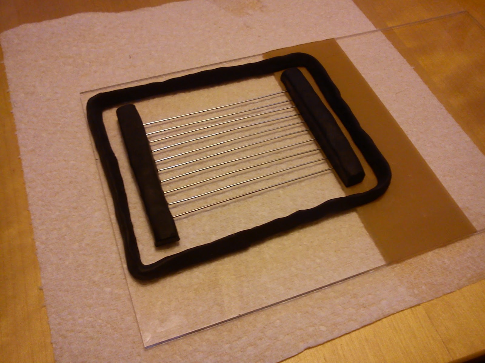
A border is added to contain the PDMS. Once the PDMS is cured the plastercine can be removed along with the right hand perspex plate. Then the overhanging PDMS can be folded to allow pliars to grab the metal wires and extract them, I HOPE. Afterwards the manifolds will be capped with more perspex of similar to seal them.

The PDMS is mixed and poured (Sylgard 184)

The bubbles seem to leave quite freely and the surface looks pretty good. I can't bake this because of the Plastercine so it will be 24hrs before cured I think nope, 48hrs. I covered it with an upturned tray to keep out the dust.
To be continued .....
Monday 18 June 2012
Solving the problem of a sticky bottom
As the previous post explains, even if your part is not glued to the bottom of the vat it may still be stuck. I'm trying to find a way around this that allows for large area printing from the bottom (FTB).
To un-stick the part from the vat bottom we need to allow fluid to get between the part and the vat. The gap between the two is so small that there is no chance for it to just seep underneath and we cannot simply drill holes in the vat and pump it in as that resin would get cured as well.
My idea is to have a number of tunnels in the flexible PDMS (silicone) vat bottom containing a fluid that has the same refractive index as the PDMS, this means optically it is as if the fluid was not there. If a negative pressure if applied to this fluid then it will distort the PDMS and that could allow fluid to flow underneath.

Hopefully the above diagram makes sense. The vat bottom is glass and the projector shines up through it. On top of that is the clear PDMS layer and then a thin layer of the light cure resin. On the left we see a part with a large surface area being printed, a small layer of resin at the top surface of the PDMS has just been cured and although the part is not glued to the silicone it can still not be lifted off without significant force. Between the glass and the PDMS are the channels filled with the index matched fluid. On the right the fluid has been evacuated and the upper surface of the PDMS has become corrugated, with the correct design of channels it should be possible to get complete separation of the part and the PDMS. It make require a small amount of time while the fluid flows beneath, it will depend on the viscosity.

Here is one way the channels might be laid out. I've suggested a diaphragm based unit to provide suction actuated by a solenoid. A spring is added to make it more gradual.

And this is another way to configure the channels, this time with a syringe type suction device.

And a few ways the channels might be created depending on the manufacturing method.
Tuesday 12 June 2012
Why does wet glass stick?
You would think that the main issue 3D printing methods that use UV cure resin and a projector shining up into the bottom of a vat would have is the parts sticking to the bottom of the vat. This is a real issue and it shapes a lot of the designs however the kind of sticking that is the real problem does not seem to be adhesive. Various materials are non-stick when it comes to the resin used, things like PTFE for example. The B9creator (way to go on over $500k pledged! to Kickstarter) uses PDMS (silicone) for its vat bottom, apparently the oxygen absorbed into the silicone reacts with the resin to form a layer that does not cure, or if not reacts the polymerisation is at least inhibited (like an anti-catalyst).
The real issue is the same sort of force you get when you press any two extremely flat objects together, especially if they are wet. One issue is atmospheric pressure, as you try to separate the plates you are increasing volume and hence decreasing pressure, the air pressure on top of the upper surface might cause a force. Then there is the viscosity of the fluid itself, if the separation occurs beneath the surface then new fluid must flow into this space.
So the idea as suggested by Michel Jullian on the group was to remove atmospheric pressure and create a print method where the base of the vat was wetted only. I decided to do some tests and here they are:

This is the simple rig. A lump of steel and a little dial indicator stand, onto the steel is glued a microscope slide (using UV cure cyno) and on top of that is placed another slide. Between the slides is pressed a little optical matching fluid which is basically an oil. Then glued on to that is an off cut from the laser cutter. Force is applied via some Kevlar thread (because I had it) and a tension spring, zip tie is obligatory for such a rig in lieu of duck tape.

The whole lot was then put in this vacuum desiccator and around 28"Hg of vacuum pulled....
Nothing happened, now I was not being extremely scientific but if it will not part with a small force then it does not help us as a technique.
I think this shows that the forces are more atomic/fluidic than atmospheric and although air could flow into the gap rather than a liquid the small layer of liquid would still have to move in some way, you can't increase volume until it does and I assume that in the same way liquids cannot be compressed they don't like to be stretched. There is probably a name for this effect but I'm not exactly sure where to start.
Monday 11 June 2012
Stika part 1, mechanical repair

This is the base with the electronics, the camera module for the scanner at the bottom and the roller with encoder and mirror a the top.

And hear the main mechanical assembly. The little gantry has a stepper driving the cutting knife with solenoid operated lift. You can see that the upper roller is not at all where it should be.

From below you can see the driven shaft that moves the paper and to the right the fixings for two springs that pull the counter roller down on to the paper. On the left the same fixings are broken and the two springs are gone. The plastic part that is missing is the rattle!

And here is the repair awaiting some springs. A little work with a dremel and a piece of piano wire were all that was required. The bearing seems to be retained well enough so I just left it. I did however end up stiffening it all up a little with some hot glue. Yep, dremel and hot glue, classy.
The unit needs a 16v supply, 16V!! Typical. It also needs a strange din connector to connect to the PC.
Pleasant surprise
This rather blurred image comes from an Ebay auction I won about a week ago. I say won, I made the first bid and nobody else bothered. Why? Well this is a vinyl cutter but a rather small one and it was sold as not working plus apparently it rattled. But I like the sound of a rattle, that is mechanical and probably easier to fix than electronics full of bespoke or obsolete parts.

Plus and importantly it was only a tenner! I got to have a look at it last night and indeed it does rattle. It looks like someone tried to force feed it some thick material and broke the mount for two springs that tension a feed roller. The springs are gone (I guess they shook them out) but the other bits are still there. It should be an easy fix. It might still be broken after that of course.
What really surprised about this machine is that it includes a scanner and what's more it actually
Thursday 7 June 2012
Tears before bed time
I ordered 10Kg of Crystacast plaster to try in the machine. Open3dp's favourite plaster is Hydroperm but I failed to find that in the UK. This plaster looks the business and indeed feels it but there are some initial problems.

It is not spreading properly and the surface is full of tears. I think that perhaps the particles are too fine or perhaps not dry enough? When I watch the powder being pushed along by the roller instead of seeing a tumbling mass like a breaking wave I see actual "waves" being formed. This is I suspect due to the non Newtonian behaviour of the powder, when compressed it acts like a solid, forms the strange lumps then tears up the surface underneath. I sieved the powder, perhaps that was my mistake?

It is not spreading properly and the surface is full of tears. I think that perhaps the particles are too fine or perhaps not dry enough? When I watch the powder being pushed along by the roller instead of seeing a tumbling mass like a breaking wave I see actual "waves" being formed. This is I suspect due to the non Newtonian behaviour of the powder, when compressed it acts like a solid, forms the strange lumps then tears up the surface underneath. I sieved the powder, perhaps that was my mistake?
Wednesday 6 June 2012
Secret ingredients
Mark from open3Dp suggested that I add about 10% glycerine to my mix to help it bond, he also suggested I try plaster instead of the starch based powder I have as a longer term solution.
I ordered some plaster that I hope will be suitable and also tried the glycerine. Firstly I noticed that it seemed to print a little darker, perhaps the cartridges prefer the modified viscosity, I don't know. After the print I left it for an hour and there was a definite improvement however it was obvious that I would not get the model out in one piece. So I lifted it out along with a lot of powder and popped it in the oven for a while to try out. The parts are definitely stronger than before but interestingly the layers do not seem to have stuck to each other.


I ordered some plaster that I hope will be suitable and also tried the glycerine. Firstly I noticed that it seemed to print a little darker, perhaps the cartridges prefer the modified viscosity, I don't know. After the print I left it for an hour and there was a definite improvement however it was obvious that I would not get the model out in one piece. So I lifted it out along with a lot of powder and popped it in the oven for a while to try out. The parts are definitely stronger than before but interestingly the layers do not seem to have stuck to each other.

Two chain links, unfortunately non of the vertically orientated links survived due to a lack of strength because of the lack of a bond between the layers.

And here we have the layers literally splitting apart. Seems a bit odd, is my saturation too low? Is the layer thickness too great? Not sure.
Bright lights
I had a bit more of a play with the laser scanning unit, this time with the laser from a Blu-ray player. These units kick out something around the 100mW range. I rather stupidly bought a new blu-ray player just to get the laser, the idea was to have something to play with over this epic 4 day weekend. Turns out I did not have the components to build a proper drive for it anyway. I decided to try it on a normal current limited PSU, a bit sketchy as I know it produces current pulses when you turn it on but I was careful. The laser did not come on! But later I found that my laser has an unusual pin out and also that it needs over 4v to get it to turn on, quite a surprise. It turned on and seems quite compatible with the scanning unit, but it was pretty bright even at 20mA so I decided to give it a rest until I get some proper goggles, better safe than sorry. Similar diodes on ebay are £7 a pop so now I am not in a rush it will be a cheaper affair all together. Also looking for a high speed driver circuit, if A4 is 210mm wide and we consider an aim of around 1200dpi then we are talking over ten thousand pulses per scan and the scanner can probably do up to 10000rpm and has 6 facets, the pulse rates are pretty high (around 10Mhz). Not sure of the best approach electrically, there are some dedicated driver chips but that might be overkill.

Yep, I've started collecting animated gifs when I see them on imgur, this one seemed to fit nicely!
Tuesday 5 June 2012
Printer poop
Here is a test mix of 30% binder by volume. Much darker than the print and has much more strength, not that it could have much less.

Homebrew
This afternoon I mixed a batch of homemade binder, this is from a recipe from open3Dp called XF1. It is basically distilled water along with some IPA and a little food colouring. It runs through the print head fine:

But alas it does not bind the power, it is no different to the distilled water that was previously installed. I'm thinking the binder was developed to work with an open source powder or I have to leave it longer or change the saturation settings or similar. Frustrating but a good test of the machine.

But alas it does not bind the power, it is no different to the distilled water that was previously installed. I'm thinking the binder was developed to work with an open source powder or I have to leave it longer or change the saturation settings or similar. Frustrating but a good test of the machine.
Monday 4 June 2012
Almost done
So I am all but done bringing the Z402 back to life, only minor issues now. To recap this is what I have had to do so far:
1. Found mispositioned ribbon cable that prevented the internal PC from booting.
4. Removed printer assembly to clean "car wash" then removed gantry to thoroughly clean.
3. Cleared blockage to input of binder filter.
4. Replaced o-rings on priming pump so it works.
5. Found damage to print head ribbon cable and repaired
6. Slow axis then failed, found problem with control relays, temporarily bi-passed.
7. Repaired binder low-level sensor, this was just a broken wire and an annoying constant error message :).
8. Replaced roller scraper, I used a piece of polypropylene from a plastic folder copying the old scraper and using a soldering iron to make neat holes (scrape off the kerf with knife).
9. Generally cleaned the heck out of it.
Yet to do:
1. Replace the relays on the interface board
2. Make or obtain binder
3. Make new gantry "curtains"
4. Work out why the laptop doesn't work.
5. Possibly replace some binder hoses.
6. Light bulb
7. Replace missing fixings
My god, it actually works!
Sunday 3 June 2012
There, I fixed it
So after some intermittent powder spreading, the slow axis (the gantry) stopped working all together. I spent the day trying to draw out the circuit for the servo stage which includes an h-bridge chip and some relays. The relays are used to interlock the axis so it cannot move when the lid is open and also to apply a brake by shorting the motor terminals. I felt sure it would be the relays but after a lot of playing still did not know how to prove it for sure, they get power but did they switch, and did I dare apply my own power to test the switching? So I decided to bi-pass, don't try this at home kids:

I have tacked the wires on to the output pins of the h-bridge and pushed them into the red connector at the bottom, I even got the polarity right (by accident). And .....
It works!! So I will order replacement relays and sort out some binder, the original Zcorp binder is crazy expensive so I will make my own. I also have 6 BC-20 ink cartridges on there way to me so I am covered there too.
Saturday 2 June 2012
"binder"
The part printed!! Well sort of.
I waited a while and proceeded with removal which involves a vacuum cleaner and a lot of care. Ooops, there goes part of the model, hang on a minute..... It looks like the bottle of binder actually just contains water! I can see that the parts printed OK but they have zero structural integrity!!
Then I came to re-spread the powder and the old issue of intermittent spreading reared its head. Not sure what it causing this, it never happens during the build and it can happen even when the feed bin is lowered and no powder is being pushed. I have added grease to the linear bearings too. Hard to diagnose the issue and no useful error messages. Perhaps the roller mech is having problems and the gantry stops because of that or perhaps there is just too much friction in the gantry but that makes no sense as it always works fine when printing. Mysterious!
I really wish I had finished my homebrew Zcorp printer, it would probably be less hassle than this ;)

The model consisted of some chain, this is part of one of the links that did not shatter, on the left impregnated with cyno on the right as it came out on the machine.
Here we go...
I know this is a blog not twitter but I am currently watching the Zcorp print and I think it will finish. There was definitely a problem with my laptop or the usb to serial converter, possibly because I had to force it to be COM1. Now using an old Dell and all seems well.
Now, I suppose I should read the manual because I am not sure what I do next :)
Now, I suppose I should read the manual because I am not sure what I do next :)
Every cloud
It looked like both of the projects I have on the go at the moment had stalled, the Zcorp because of a lack of an ink cartridge and the laser scanner because of a lack of component availability. So I settled to have a weekend doing all of the things I should have been doing this past week. I emptied a ton of rubbish from my car, emptied the bins and even started to look at the washing up. While considering which box I could use to tidy up all the Zcorp bits into I noticed a small cardboard box, could it be, no don't get your hopes up, YES another cartridge, an original zcorp spare even! . . .


OK I got a little excited taking off the protective cap!

Success! Well another good step, this is printed in binder and it seems to have worked. I have a few powder spreading issues, I definitely need to replace the scraper on top of the roller/spreader but it's better, definitely better. But then .....

Nooooo! This has happened a few times, might be the PC end not the machine, will try again and then with another PC.
Friday 1 June 2012
Better than nothing
The results of replacing the repaired ribbon cable are promising. Perhaps I killed the cartridge running it with the broken cable and so only some jets are firing? I will try again with the proper cart and binder.

This is a layer from the middle of a demo object consisting of a chain and a little disk stating the build time. But it should not be so stripy!
Micro surgery
So here is how one repairs a flex PCB, well at least I think it is repaired, the proof will be in trying it on the 3D printer. Photos are from my phone peering into the eye piece of a stereo microscope.

Well, there is one very obvious break! The line above was also broken at the point where the Kapton covering ends. I made two light cuts through the tape and peeled it back and trimmed it. Then I scraped any remaining adhesive from the tracks.

Now the tracks were tinned with a lead/tin/silver solder, it is the thinnest I have at 0.5mm and a lower melting point than most.

To make the repair I took a single strand of tinned copper wire from a piece of multicore hook up wire and flattened it in smooth pliers, then I tinned it and soldered it in place using a flux pen to ensure the solder flowed even if it took me a while. I flattened the wire because I was worried that it might sit higher than the little nipples that form the contacts. So that is two done, finished! Yeah right.

On higher mag I could see that this poor line had a further two breaks!

Much clearer when the Kapton is peeled back

This time I used a thinner wire from the multicore that is found in mice leads. It is really nice wire for many projects so save those mice cables! Here you can see how I made a little handle using the wire, if the wire and tracks are tinned you just need to press down with the iron and they bond, extra flux does help. The wire was trimmed by placing the scalpel on it before wiggling it a little, remember this is super thin stuff!

The other repair was on a bend and does not look so pretty. This joint and the others where carefully shaved with a scalpel to reduce their height, probably not needed but did not hurt.

All done! Well not quite, when I found someone to assist I did electrical tests from the other end of the ribbon to this end and found two more breaks, again always at the boundary of the Kapton, this is simply where stress concentrates. I hope it works after all this effort. If it does I can start looking for an old printer to ravage.
Thursday 31 May 2012
Seek and ye shall find.
I had what I thought was a good idea, put a normal ink cartridge in the 3D printer, one with ink in and then see if it would print, that would rule out binder issues and perhaps I would get to see some printing. The printer's cartridges are based on Canon BC-20's and they simply decapitate them, remove the ink and wadding and glue a plastic screw top vial that has had its bottom cut off over the hole in the bottom of the cartridge. These vials have a screw cap which is compatible with the machine hose lines. I was given a bag of the vials so just hooked the lines to an empty one, it certainly proved that the binder pumps OK. But alas still no joy, now I was getting errors, too many deprimes! This seems to be when the fluidic connection between the reservoir and nozzle is lost, seemed unlikely it was caused by the fresh out of the package ink cartridge. A guy on the forum suggested it might be the flex pcb type ribbon cable that runs to the cartridge so I took it off and had a look. And it seems it is definitely damaged.


This is the part that contacts with the cartridge. Now let's get all CSI on its ass, zoom in on sector D5.

And there is our problem, one of the tracks has broken and even peeled back, now give me a hard copy of that. But BladeRunner references aside the cable and I have a date under the stereo microscope with some very thin wire and a very small soldering iron. I'd better lay off the caffeine now! Fingers crossed this is the issue because I am so close now to printing something.
Spinnage is good for you
I managed to get the polygon mirror scanner rotating nicely, it was actually very simple once I convinced myself I had the right pin out. Then I tried to get the laser to fire up, this time it was a little harder because I only have printer service manuals to go by, I think I got the right connections but failed to get it to fire. I may have damaged the laser. Anyway it doesn't really matter as that laser is of the wrong wave length, would have been nice though.
Wednesday 30 May 2012
Scanning based 3D printer
Talk on the diy_3d_printing_and_fabrication Yahoo group has turned recently towards the possibility of using the polygon scanning mirror and lenses from a laser printer to create a resin based 3D printer for large areas. The scanner scans a line with a laser and then you move the scanner to "develop" a layer, then repeat. Basically the same idea as a SLA or DLP based resin projector just a different method of imaging. A few guys have done this sort of thing to try and image PCBs directly in photoresist. The visible light curing resins that can be used in 3D printers may however work a lot better than the etch resist.
I have a Samsung laser printer with a perpetual paper pick up problem so decided to take it to bits to investigate. It is a pleasingly simple module, pictures now follow.


The other side

At the bottom left we have the spinning mirror, at the top is the weird looking lens that corrects for the variation in distance from the mirror to the drum in the printer, probably does some focussing too, not sure.

This is a brushless motor controller by Rohm especially designed for polygon scanners. The control is very simple from what I have managed to work out, there is a clock to set the speed, a start/stop input and an output to say then the PLL has a lock (i.e. the speed is constant). Then power which is 24v (up to 36 but I suspect 24).

The optics consist of a collimator, a metal aperture and then a focussing lens with a long focal length. The mirror is very thin so perhaps the aperture stops stray reflections from other parts of the motor.


I have a Samsung laser printer with a perpetual paper pick up problem so decided to take it to bits to investigate. It is a pleasingly simple module, pictures now follow.

The scanning module as it is found in the printer, very possibly this is a part obtained from a 3rd party. It is a really neat sealed unit just waiting to be mounted into a machine.

The other side

At the bottom left we have the spinning mirror, at the top is the weird looking lens that corrects for the variation in distance from the mirror to the drum in the printer, probably does some focussing too, not sure.

This is a brushless motor controller by Rohm especially designed for polygon scanners. The control is very simple from what I have managed to work out, there is a clock to set the speed, a start/stop input and an output to say then the PLL has a lock (i.e. the speed is constant). Then power which is 24v (up to 36 but I suspect 24).

The optics consist of a collimator, a metal aperture and then a focussing lens with a long focal length. The mirror is very thin so perhaps the aperture stops stray reflections from other parts of the motor.

The collimator

The laser diode, a simple uncollimated source. At the very top you can also see a photodiode which is used to sync the control signals to the diode with the rotation of the mirror. The beam hits a small mirror at the other end of the correction lens and then shoots over to this sensor.
Should be quite easy to get a basic system up and running, I'll probably use the propeller microcontroller which should eat the task up but I will need a UV laser to do some real tests, not to mention some resin. And I have the Zcorp to finish! Argh, maybe tomorrow!
Subscribe to:
Posts (Atom)